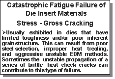
 In Part 1 of our series on “Modes and Causes of Die Failure” we began our examination of Stress and Thermal Fatigue by discussing die heat checking. We also know that Gross Cracking is another type of failure which is
usually catastrophic and caused by the die material’s loss of toughness. The above statement identifies and explains some contributing factors that can exacerbate gross cracking failure. In Part 1 of our series on “Modes and Causes of Die Failure” we began our examination of Stress and Thermal Fatigue by discussing die heat checking. We also know that Gross Cracking is another type of failure which is
usually catastrophic and caused by the die material’s loss of toughness. The above statement identifies and explains some contributing factors that can exacerbate gross cracking failure.
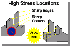
Unfortunately, sometimes design requested criteria or needed dimensions and tolerances as specified by end user drawings and prints call out sharp corners or edges. These sharp corners, are, by nature, high
 stress areas. As a result, gross cracks are more likely to start in these areas. For this reason, wherever possible, inside and outside tooling corners and edges should be designed to have radii. stress areas. As a result, gross cracks are more likely to start in these areas. For this reason, wherever possible, inside and outside tooling corners and edges should be designed to have radii.
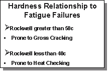
A general rule of thumb for hardness is: Harder dies are more prone to gross cracking. Conversely lower rockwells are less likely to gross crack but too low of hardness can cause the tool to prematurely heat check. The optimum for dies is anywhere between45-48Rc. Sometimes larger inserts tend to have lower than 45Rc hardness. The
reasoning behind this is that gross cracking of large tools is more costly than heat checking. Smaller inserts conversely are sometimes targeted to higher than 48Rc to protect against heat checking which is sometimes unacceptable for
intricate and small design configurations. It is important to note that rockwell hardness is NOT the only determinate of proper heat treating. is sometimes unacceptable for
intricate and small design configurations. It is important to note that rockwell hardness is NOT the only determinate of proper heat treating.
|
Charpy impact values are also critical in determining a die’s toughness and can make or break (no pun intended) the tool. Charpy V-Notch levels should average 8ft lbs. It is possible to have a 44-48Rc die that still has poor charpy impact values. NADCA’s Premium Quality H-13 Steel Acceptance Criteria for Pressure
Die Casting Dies #207-90 covers the aspects of proper steels election including: composition, hardness, micro cleanliness, minimum Charpy V-notch impact values, grain size, and annealed microstructure.
Another cause of fatigue cracking is Electrical Discharge Machining (EDM) techniques. Today a majority of die casting die inserts are produced using this system. EDM uses a series of electrical spark discharges that melts or vaporizes the contacted metal. The rapid subsequent re-solidification of this melted contact area leaves
the surface with an altered micro structure and high residual stresses which
 can lead to both premature heat checking and gross cracking failure. It is important that the EDM process be performed in a manner to reduce these conditions as much as possible. The cross
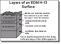
section diagram shown here depicts the various surface layers and their relative thickness in microns. Aggressive EDM procedures increase the relative thickness of these layers. The top layer which is sometimes referred to as the “white cast” MUST BE REMOVED by polishing or electro-chemical methods. This layer is riddled with cracks and is much harder as a result of
the re-hardening of the surface. The thickness of both the recast and re-hardened layers increases with spark duration. The recast white layer and softened layer appear to always be present, however, the presence of the untempered martensite is dependent on the EDM treatment. MetaLL- ifeÒ closes the cracks that propagate below the recast and hardened layer, increases needed fracture toughness, and restores compressive stress benefits. For a full report, request our bulletin. ”EDM Effects on H-13 Steel” either by Phone, Fax, or Email from our Guestbook Website. can lead to both premature heat checking and gross cracking failure. It is important that the EDM process be performed in a manner to reduce these conditions as much as possible. The cross
section diagram shown here depicts the various surface layers and their relative thickness in microns. Aggressive EDM procedures increase the relative thickness of these layers. The top layer which is sometimes referred to as the “white cast” MUST BE REMOVED by polishing or electro-chemical methods. This layer is riddled with cracks and is much harder as a result of
the re-hardening of the surface. The thickness of both the recast and re-hardened layers increases with spark duration. The recast white layer and softened layer appear to always be present, however, the presence of the untempered martensite is dependent on the EDM treatment. MetaLL- ifeÒ closes the cracks that propagate below the recast and hardened layer, increases needed fracture toughness, and restores compressive stress benefits. For a full report, request our bulletin. ”EDM Effects on H-13 Steel” either by Phone, Fax, or Email from our Guestbook Website.
The special March bulletin issue will feature a schematic analysis of the Mechanism of Die Heat Checking, along with Professor Wallace’s “K” factor for optimizing Thermal Fatigue Resistance.
|
