|
Print this Newsletter
Badger Metal Tech, Inc. N60 W15088 Bobolink Ave. Menomonee Falls, WI 53051 262-252-3804 FAX 262-252-3956 TOLL FREE in the United States and Canada - 800-366-1973
| Volume 4 Issue 3 |
Modes & Causes of Die Failure
Part 3 |
March 1997 |
Our examination of the modes and causes of die failure due to cracking have shown two types of failure -heat checking and gross cracking. The Figure 1 schematic shows a cross section of a die and the stress physics associated with thermal or heat check cracking. Molten metal contacts the die and causes the surface temperature to increase
more than the interior of the die. The die face (Diagram1) starts to expand, however, the cooler underlying layer resists. This creates a temporary compressive stress layer. When the casting is removed, the die surface starts to cool (Diagram 2) and as it does, the surface shrinks. The surface cools more quickly, however, than the interior of the die which places the
die’s sub-surface in residual tension stress which is exacerbated (Diagram 3) by the application of die lubricant. The curved dotted line in each drawing shows the relative difference in temperature for the interior of the die.
 |
Continued cycling of the die, as shown in Figure 2, eventually reduces the yield strength of the tool which causes subsequent higher residual tensile stresses to develop and along with this, the initiation of the all too common thermal stress cracks. This type of cracking is more prevalent in aluminum and brass die
casting tools due to the high contact temperature and resulting thermal shock of the molten metal and alloys used. Premature escalating heat checking is averted by good steel selection, proper heat treatment, and preventative maintenance measures. Periodic heat stress tempering is usually performed at 50 degrees F (1050 to 1000 degrees F) below the last temper to remove the cyclical residual
tensile stresses. Subsurface compressive stress attributes also need to be maintained to counter the subsequent build-up of tensile stresses on the |
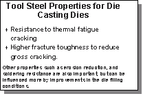
 If we summarize the two previous bulletins, the steel properties shown at left become critical to assuring maximum die cast tool life and protec ton against die thermal fatigue and gross cracking. If we summarize the two previous bulletins, the steel properties shown at left become critical to assuring maximum die cast tool life and protec ton against die thermal fatigue and gross cracking.
After steel selection and tooling of the die, proper heat treatment is the most important step to assuring long tool life. The Jan/Feb issue of Die Casting Engineer has an excellent article by FPM’s John A. Fitzgerald on page 34. We recommend this as required reading for all die casters concerned about premature die failures. Preventive and corrective
action to remove residual stress build-up and minimize softening of the die’s surface contribute to a high level of resistance to fatigue failure from thermal stresses. The preventative maintenance should include regular heat stress tempering, and MetaLL ifeÒ Compressive Stress Topography. Initial
|
application should be done when the die is
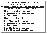
 NEW after final sample approval and then periodically throughout the life of the tool. A review of the “K” value formula presented by Professor John Wallace from Case Western
Reserve University shows that a high yield strength at temperature results in a higher “K” value which is one of the proven benefits of MetaLL ifeÒ. NEW after final sample approval and then periodically throughout the life of the tool. A review of the “K” value formula presented by Professor John Wallace from Case Western
Reserve University shows that a high yield strength at temperature results in a higher “K” value which is one of the proven benefits of MetaLL ifeÒ.
In our next special issue in April, we will discuss other considerations to obtaining a high “K” value and show how MetaLL ifeÒ assists in some of these areas. Future issues, will discuss some new and important developments for
alternatives to H-13 tool steel, along with the results of initial studies on the use of coatings to help control the second largest cause of die deterioration - Soldering and Chemical Attack.
|
This page was updated -
April 03, 2010
|
